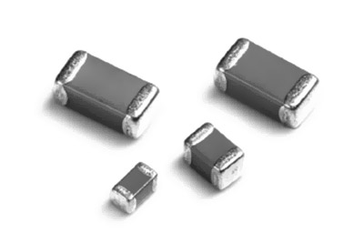
What is a MLCC and What is it used for?
What is a MLCC and What is it used for?
Classification of MLCC
1. NPO MLCC
2. X7R MLCC
3. Z5U MLCC
4. Y5V MLCC

Difference: The main difference between NPO, X7R, Z5U and Y5V is their filling medium. Under the same volume, the capacity of the capacitors composed of different filling media is different, and the dielectric loss and capacity stability of the capacitors are also different.
MLCC
The internal structure of chip capacitors
Its appearance is made of ceramics, but there is more than one kind. It is also divided into glass capacitors, oil-paper capacitors, and electrolytic capacitors.
The so-called ceramic chip capacitors are usually referred to as MLCC, that is, multilayer ceramic capacitors (Multilayer Ceramic Capacitors).
Conventional chip capacitors are divided into COG (NPO), X7R, Y5V according to materials, and their pin packages are 0201, 0402, 0603.0805.1206, 1210, 1812, 1825, 2225.
Multilayer ceramic capacitors (MLCCs) are stacked by parallel ceramic materials and electrode materials.
The role of chip capacitors
1. Bypass
Bypass capacitors are energy storage devices that provide energy to local devices, which can equalize the output of the voltage regulator and reduce load demand. Like a small rechargeable battery, the bypass capacitor can be charged and discharged to the device. To minimize impedance, bypass capacitors should be placed as close as possible to the power and ground pins of the load device. This is a good protection against ground potential rise and noise caused by excessively large input values. Ground potential is the voltage drop across a ground connection when a large current spike is passed through it.
2. Decoupling
Decoupling, also known as decoupling. From a circuit perspective, a distinction can always be made between the source of the drive and the load being driven. If the load capacitance is relatively large, the drive circuit needs to charge and discharge the capacitance to complete the signal transition. When the rising edge is relatively steep, the current is relatively large, so the driving current will absorb a large power supply current. The inductance and resistance (especially the inductance on the chip pins will bounce back), this current is actually a kind of noise compared to the normal situation, which will affect the normal operation of the front stage, which is the so-called "coupling.
The decoupling capacitor is to play the role of a "battery" to meet the change of the drive circuit current and avoid mutual coupling interference.
It will be easier to understand by combining bypass capacitors and decoupling capacitors. The bypass capacitor is actually decoupling, but the bypass capacitor generally refers to a high-frequency bypass, that is, to provide a low-impedance leakage prevention path for high-frequency switching noise. High-frequency bypass capacitors are generally small, generally 0.1μF, 0.01μF, etc. according to the resonant frequency; and decoupling capacitors are generally larger, maybe 10μF or larger, depending on the distribution parameters in the circuit and the change in drive current to make sure. Bypass is to filter out the interference in the input signal, while decoupling is to filter out the interference in the output signal to prevent the interference signal from returning to the power supply. This should be their essential difference.
3. Filtering
Theoretically (i.e., assuming that the capacitor is a pure capacitor), the larger the capacitor, the smaller the impedance and the higher the passing frequency. But in fact, most capacitors exceeding 1μF are electrolytic capacitors, which have a large inductance component, so the impedance will increase when the frequency is high. Sometimes it is seen that there is a large electrolytic capacitor connected in parallel with a small capacitor. At this time, the large capacitor passes the low frequency, and the small capacitor passes the high frequency. The function of the capacitor is to pass high resistance to low, pass high frequency to block low frequency. The larger the capacitance, the easier it is for low frequencies to pass. Specifically used in filtering, a large capacitor (1000μF) filters low frequencies, and a small capacitor (20pF) filters high frequencies. Some netizens once compared the filter capacitor to a "pond".
Since the voltage across the capacitor will not change suddenly, it can be seen that the higher the signal frequency, the greater the attenuation. It can be said that the capacitor is like a pond, and the water volume will not change due to the addition or evaporation of a few drops of water. It converts changes in voltage into changes in current. The higher the frequency, the greater the peak current, thereby buffering the voltage. Filtering is the process of charging and discharging.
4. Energy storage
The energy storage capacitor collects the charge through the rectifier, and transmits the stored energy to the output terminal of the power supply through the converter lead. Aluminum electrolytic capacitors (such as B43504 or B43505 from EPCOS Company) with a voltage rating of 40-450VDC and a capacitance value of 220-150 000μF are commonly used. According to different power supply requirements, devices are sometimes used in series, parallel or a combination thereof. For power supplies with a power level exceeding 10KW, larger pot-shaped screw-terminal capacitors are usually used.


 English


