Solid State Technology: An Overview
Solid State Technology: An Overview
If you’re old enough to have owned a portable CD player, you might remember how the music would skip if the CD got scratched or dirty. Or maybe you remember how VHS tapes had winding issues, tape deterioration and poor image quality. Flash memory made these complicated mechanical storage methods obsolete by providing an affordable solid-state solution.
In the automotive industry, manufacturers are currently tackling the issue of how to clean cameras and sensors by implementing miniature wipers, spray jets, pressurized air and other systems. But it’s unlikely that these solutions will proliferate – they are expensive and mechanically complex.
The solid-state solution in this case is ultrasonic lens cleaning (ULC), enabling cost-effective self-cleaning of cameras and sensors.

Learn more about
|
|
Improve camera reliability with solid-state sensor cleaning for machine vision systems. |

Given the great number of lens sizes and materials, there are many structural approaches for ULC. And how do semiconductors play a role? For simplicity of this article, let’s look at water as a contaminant on a typical circular camera, although ULC is not limited to this.
To clear a lens, you can either create a force to move water across the lens outside the field of view (FoV), or accelerate water to the point of atomization with a force stronger than the surface tension. As described in my earlier technical article, “what is Ultrasonic Lens Cleaning Technology?”, ULC leverages the concept of constructive interference through resonance, amplifying energy from microscopic vibrations into energy strong enough to move or atomize water. Hydrophobic and oleophobic coatings are an effective way to reduce lens polarity, optimizing the performance of ULC systems.
Actuation
For appropriate vibration, an actuator must create the necessary forces, have a wide bandwidth and a small form factor, and be cost-effective. Piezoelectric actuators, commonly called piezo transducers, meet these requirements and are reliable enough for military and automotive applications. Polarized piezo material changes shape when applying a voltage potential to its plated surfaces. If the voltage potential is AC in nature, then the piezo material will resonate at the frequency of the AC signal. Thus, piezo transducers are effective actuators for generating vibration in ULC. Figure 1 shows two different geometries of piezo material being actuated for vibration in slow motion.

Figure 1: Animation of piezo transducers being actuated in slow motion
Cleaning
A simple approach resonates the lens at one of its natural frequencies to create a standing wave known as a mode. The high acceleration level on the surface expels the water. A typical frequency for driving a mode on a circular glass lens that’s 10 mm to 40 mm in diameter and 0.5 mm to 2 mm thick is usually between 20 kHz and 100 kHz. Since the resonance frequency changes slightly with contaminants, a cleaning cycle may sweep a few kilohertz around the natural frequency of the lens. For example, if the natural frequency is 30 kHz, a ULC system could sweep from 28 kHz to 32 kHz to ensure proper cleaning. A drawback of single-mode cleaning is the acceleration gradient; lower acceleration points may clean poorly and leave visual residue. Figure 2 shows the simulation of a single mode cleaning system and its acceleration gradient, highlighting this drawback.

Figure 2: Simulation of a single-mode cleaning system and its acceleration gradient
Bimodal cleaning, shown in Figure 3, is an advanced ULC approach that leverages two different standing waves in consecutive cleaning cycles. This approach helps eliminate dead spots, or spots with little to no cleaning effect, to ensure full coverage.

Figure 3: Simulation of a bimodal cleaning system and its acceleration gradients
Another ULC approach uses surface acoustic waves (SAWs) that do not directly vibrate the glass pane. Instead of creating a standing wave for expulsion, SAWs travel along the surface and energize contaminants directly for propulsion. The SAW approach requires much higher frequencies and multiple actuators per glass pane, making them more complex and costlier than direct lens vibration. However, this approach works on larger surfaces and rectangular panes (such as lidar windows) better than direct vibration. And since SAWs travel on the surface, this approach also requires less energy than vibrating a large, thick lens.
Lens cover system
One method of ULC invented by TI involves a bracket to interface a uniformly thick lens with a ring-shaped piezo transducer. Ring transducers take up little additional space, and the bracket eliminates any direct glass-to-piezo contact – which can be challenging to bond – enabling a scalable manufacturing process with reliable results. This assembly is called a lens cover system (LCS) because it sits compactly over the camera lens, similar to the flat glass window you can see over smartphone cameras. A curved LCS can accommodate large FoVs with minimal optical distortion, as shown in Figure 4.

Figure 4: A curved LCS with a >190-degree FoV
Fully integrated ULC
It’s possible to implement ULC directly in a camera module without a lens cover by actuating the final camera lens itself. This final camera lens is known as the front element, shown in Figure 5. Integration would reduce overall system size compared to adding a lens cover, but would add complexity to ultrasonic cleaning and manufacturing, partly because the front element is nonuniformly thick – which inhibits the creation of an adequate standing wave, as in single-mode or bimodal cleaning. A front element may need to be nonuniformly thick in order to refract light into the optical sensor, but a cover lens can be uniformly thick, since it only serves to protect the camera. Furthermore, since the front element is part of the camera lens stack, it needs to be precisely aligned over the optical sensor during manufacturing, complicating the design flow and manufacturability of a fully integrated ULC system.

Figure 5: An example of a lens stack in a camera barrel
The role of semiconductors
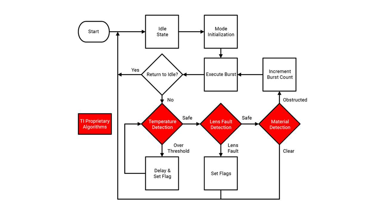
Application-specific standard products (ASSPs), such as TI’s ULC1001, reduce cost and size by combining multiple functions in one device. Given differing manufacturing variabilities, housing assemblies and installations, every individual lens will have a different natural frequency that will change slightly over its lifetime. ULC1001 can characterize a lens system at any point to increase effectiveness. Another integrated function is temperature sensing, which can help facilitate the detection and clearing of ice, but is even more important for the preservation of piezoelectric functionality. If the Curie temperature threshold is exceeded, a piezo transducer will depolarize and lose its resonant properties. The ULC1001 can monitor the temperature of the piezo transducer to ensure that it’s not driven past the Curie point and can also check for any lens faults, such as a chip or crack from debris. With an integrated digital signal processor and a closed feedback loop, the ULC1001 enables automatic contaminant detection and cleaning without image processing. The new lens cleaning IC implements these features with a state machine such as the example shown in Figure 6, customizable for a given application.

Figure 6: A simplified example of a ULC state machine
Let’s make waves
While ULC is complex and multifaceted, TI has established a foundation for the technology that includes open-source mechanical designs and purpose-built semiconductors. I invite you to explore ULC design resources and make waves in the automotive and industrial markets – to have better, smarter, more affordable cameras with self-cleaning capability.


 English


